Transforming a 3D CAD model into high-performance elastomer components demands far more than basic tooling. The modern rubber manufacturing process bridges precision engineering with material science—where early-stage decisions in elastomer selection, shrinkage calculation, and mold geometry dictate your unit cost, cycle times, and dimensional stability.
In custom OEM rubber production, precision tooling represents a significant capital investment. Unlike rigid plastics, elastomeric behavior introduces complex variables in material flow, gate placement, and flash control. Once steel is cut, retrospective modifications become costly and delay launch timelines. This comprehensive guide walks through the critical stages of the rubber molding process—from DFM (Design for Manufacturability) to scalable mass production—highlighting the engineering controls that prevent costly tooling revisions and protect your bottom line.
You begin the rubber manufacturing process with formula design. Engineers select raw polymers and mix them with curing agents, fillers, and plasticizers. This step, called compounding, determines the material's final properties. Next comes mold design and tooling fabrication. You then move to prototyping and validation before full-scale production.
Beyond standard molding, the rubber product manufacturing process also includes extrusion for continuous profiles and calendering for sheet goods. Each path shares the same core logic: prepare the compound, shape it, and cure it through vulcanization. Handling these interdependent stages under one roof helps streamline quality control and keep production on schedule.
A typical timeline breaks down into three phases. Design and prototyping take 2–4 weeks. Mold fabrication requires 4–6 weeks. Production and delivery follow 2–3 weeks after mold approval. These timelines help you plan resources and set realistic launch dates.
Vulcanization is the chemical process that gives rubber its final properties. Heat and curing agents create crosslinks between polymer chains. This network transforms soft, sticky material into a durable, elastic part. Without vulcanization, rubber parts would fail under stress and heat.
Several factors influence the outcome. Using a low-temperature, long-time vulcanization cycle forms a polysulfide network. This achieves higher sulfur crosslink density and results in higher tensile strength. Replacing MBS or TBBS with CBS in natural rubber compounds can also provide higher tensile strength and elongation at break. A conventional vulcanization system with polysulfide bonds delivers higher tensile strength compared to efficient vulcanization with monosulfide or disulfide bonds.
Your material choice defines how a part behaves in engine, electrical, chassis, cooling, and fuel systems. The rubber compounding step combines raw polymers with curing agents, fillers, and plasticizers. This compounding process tailors the material properties for each application. A well-executed rubber compounding step directly influences performance.
Choosing between nitrile and EPDM rubber requires a clear understanding of operating conditions rather than relying on material familiarity alone. Oil exposure, temperature range, chemical contact, and environmental factors all influence long-term sealing performance. When the correct rubber compound is matched to real service requirements, seals and gaskets last longer, perform more consistently, and reduce maintenance costs.
You must match material to the worst-case condition. Use lab or field-tested data for your specific media. Consider hybrid materials for applications with multiple stresses. Factor in lifecycle cost, not just raw material price. A comparison table helps you visualize options:
| Material | Best For | Durability Level |
| EPDM | Weather, UV, water | High |
| NBR | Oil, fuel | Medium |
| Silicone | Heat, cold | High |
| Viton (FKM) | Chemicals, pressure | Very High |
FKM delivers outstanding high-temperature performance. It offers continuous service up to 200°C. Its compression set after 70 hours at 200°C is ≤20%, compared to NBR which exceeds 60%. This durability reduces replacement frequency and lowers total cost of ownership. For high-temperature engine applications, FKM provides unmatched durability. Its low compression set and excellent chemical resistance make it ideal for oil seals and O-rings. By matching the right rubber compounds to your operating environment, you extend equipment life.
Once you select the material, you must focus on tooling design. Mold design is one of the most important steps in the entire process. Poor mold geometry can ruin even the best rubber compound.
Three factors dominate mold design: shrinkage, draft angles, and parting lines.
Rubber shrinks as it cures and cools. Each material has a specific shrinkage rate. Your mold must be oversized to compensate. If you ignore shrinkage, the final part will not meet dimensional tolerances. This is especially critical for seals and gaskets that require tight fit.
Draft angles allow the part to release from the mold. Without sufficient draft, parts stick and deform during ejection. The angle depends on material hardness and geometry. Typical values are determined by material hardness and geometry.
Parting lines are the seams where mold halves meet. They affect flash formation. A well-designed parting line minimizes flash and reduces secondary trimming. It also influences the ease of tooling fabrication and maintenance.
These considerations affect your design for manufacturability. By thinking ahead about the mold, you avoid costly mold modifications later. Integrated tooling and manufacturing ensures that design and production work together from the start.
A capable manufacturing partner excels in custom rubber mold making by maintaining fully in-house tooling facilities. In-house mold fabrication gives manufacturers precise control over cavity tolerances, surface finishes, and delivery lead times. When tooling and production operate under the same roof, engineering teams can rapidly iterate prototypes, fine-tune parting lines, and adjust dimensions based on initial CMM inspection data. This close collaboration eliminates communication bottlenecks between external toolrooms and production floors, speeding up time-to-market while safeguarding repeatable batch-to-batch quality.
Furthermore, qualified manufacturers bring cross-process expertise to recommend the right mold architecture—whether designing single-cavity compression tools for low volumes or balanced multi-cavity injection molds for high-throughput programs. Designing durable, hardened tooling tailored to the specific molding method not only reduces long-term maintenance costs, but also prevents unexpected downtime.
Attention to these factors in the mold design phase prevents production delays and ensures your rubber parts meet stringent automotive standards.
You have several options for building prototypes. Carbon DLS uses real polyurethane to yield production-quality rubber parts with consistent isotropic properties. Elastomeric materials are available in durometers from 35A to 88A. Silicone casting requires a master part, mold creation, and casting. This method is unmatched for producing many prototype parts. Mold creation can now take less than two days, but the overall process remains long even for a single elastomer prototype.
Prototype mold construction offers another path. Prototype molds require a significantly lower initial investment than production tooling. Costs vary widely depending on complexity and material, with simple 3D-printed molds being much less expensive than machined aluminum molds. Production tooling often costs orders of magnitude more. Prototype tooling typically accounts for only a fraction of overall production tooling costs. This upfront savings directly reduces validation costs. You can iterate without large capital outlay.
Prototype molds are typically CNC machined from softer metals like aluminum or brass. These metals are less expensive to machine and allow faster turnaround. Their single-cavity design makes it easier to modify geometry. Only one cavity needs adjustment. This simplicity avoids the complexity and cost of multi-cavity hardened steel molds. Modifying a simplified aluminum mold is much easier and cheaper than reworking a multi-cavity hardened steel production mold. The prototype phase becomes rigorous engineering validation that prevents costly production tool revisions.
You must validate prototypes against international standards. ASTM and SAE provide classification systems for rubber materials. These standards help you specify rubber parts in automotive applications. The ASTM and SAE line call-out is a standard method for defining material properties and test requirements.
Validation also covers fit and function. You check dimensions, compression set, and chemical resistance. The information gained during prototype molding leads to a final design that requires far fewer revisions to the production tool. This saves both time and money on the back end of the project. A well-validated prototype confirms your mold design and your design for manufacturability before you commit to full production.
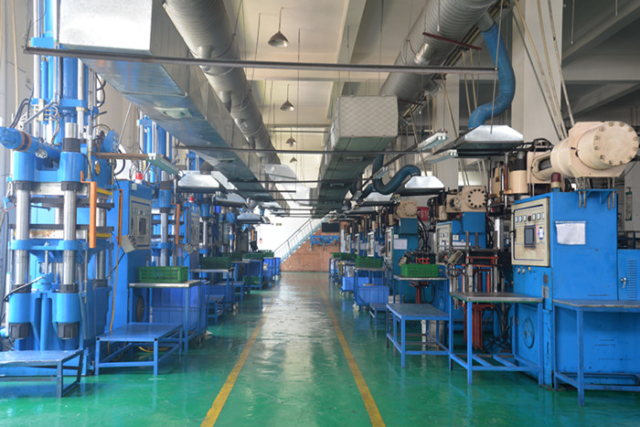
You now move from validated prototypes to full-scale output. The rubber product manufacturing process offers three main paths for mass production. Each method suits different volumes, geometries, and budgets. Your choice affects cycle time, tooling cost, and part consistency.
Compression molding places uncured rubber directly into a heated mold cavity. The mold closes under pressure. Heat and pressure shape the material and trigger vulcanization. This method works well for simple shapes and low-to-medium volumes. You get lower tooling costs compared to other rubber molding techniques.
Cycle times vary by part geometry and material. General compression molding involves stages including preheating, material loading, mold closing, curing, cooling, and part ejection, each taking a variable amount of time.
Advanced heating systems and pressure optimization can achieve faster cycle times compared to traditional methods. This speed matters when you scale up.
Transfer molding uses a transfer pot for more complex shapes. You place uncured rubber in a chamber above the mold cavity. A plunger pushes the material through a sprue into the cavity. This approach handles intricate geometries better than compression molding. It also reduces flash and improves dimensional control.
Injection molding injects preheated rubber into a mold cavity. The process automates material feeding, injection, and curing. You achieve faster cycle times and tighter tolerances. Material waste drops significantly.
Its automated nature makes it the go-to approach for intricate designs and demanding applications where consistency is paramount. Manufacturers favor this method for high-volume production runs because it delivers consistent, reliable results and minimal scrap. This process particularly suits complex parts, delivering repeatable quality across millions of units to easily support demanding automotive and industrial programs.
Other rubber product manufacturing processes include extrusion and calendering. Extrusion shapes continuous profiles through a die, making it ideal for hoses, seals, and weatherstripping. Calendering produces continuous sheets by passing rubber through precision rollers, which suits flat gaskets and lining materials. Each manufacturing path requires dedicated tooling and specific processing expertise.
Your choice among these methods depends on volume, part complexity, and material. Compression molding offers simplicity and low tooling cost. Transfer molding balances complexity and tooling investment. Injection molding delivers unmatched speed and consistency for high-volume production. Relying on integrated in-house tooling and mold design capabilities helps support all three approaches, ensuring your project moves smoothly from initial prototype to full output.
Consistency separates a reliable supplier from a risky one. Established manufacturers maintain repeatable quality across production runs through dedicated facility scale and skilled teams. This infrastructure supports strict process controls at every station, ensuring identical part performance whether producing hundreds or millions of units.
The rubber manufacturing process demands precise control over cure time, temperature, and hydraulic pressure; slight deviations can alter finished dimensions, durometer hardness, and tensile strength. Manufacturers like Fuste address this challenge through standardized work instructions, continuous cavity monitoring, and rigorous in-process inspection. By subjecting each batch to dimensional verification and rheometer testing under certified quality management systems (such as ISO 9001 and IATF 16949), complete traceability is maintained from raw compound to finished packaging, providing the compliance documentation high-reliability industries require.
Scaling from prototype to mass production requires a structured engineering roadmap rather than merely adding press capacity. A proven scale-up framework typically advances through five stages: prototype validation for geometry and fit, engineering verification testing (EVT) on pilot batches, design verification testing (DVT) for process capability, production verification testing (PVT) to audit cycle times and tooling wear, and finally, full-scale mass production.
By applying this structured discipline alongside pilot runs and formal audits, Fuste helps engineering teams de-risk the ramp-up phase. This systematic oversight ensures that high-volume output retains the exact mechanical tolerances established during initial sampling—whether the component is produced via molding, extrusion, or calendering.
Navigating the critical path from compound selection and mold design to mass manufacturing directly dictates part longevity and overall program ROI. Material choice defines environmental resilience, while disciplined tooling design safeguards dimensional accuracy and eliminates parting-line flash.
Achieving repeatable results at scale ultimately relies on tight alignment between material scientists, mold engineers, and production crews. Integrated manufacturers like Fuste bring these disciplines under one roof, eliminating cross-vendor finger-pointing and preventing expensive tooling rework after steel is cut. With a clear view of the rubber manufacturing lifecycle, you can better qualify OEM partners, optimize molding methods for your production volume, and scale into full-rate production with total confidence in batch-to-batch consistency.
Design and prototyping take 2–4 weeks. Mold fabrication requires 4–6 weeks. Production and delivery follow 2–3 weeks after mold approval. These timelines help you plan resources and set realistic launch dates. Early decisions on design and material affect your final cost and part quality.
Common compounds include EPDM (weather and ozone resistance), NBR/HNBR (oil and fuel resistance), Silicone (high/low temperatures), and FKM (extreme heat and chemical exposure). Compound selection depends directly on your operating environment.
Automotive and industrial components typically adhere to ISO 9001 or IATF 16949 standards, supported by ASTM D2000 material specifications, First Article Inspection (FAI) reports, and dimensional CMM checks.
Compression molding offers the lowest tooling investment for low-to-medium batches. Injection molding requires higher initial tooling costs but delivers the lowest unit price, fastest cycles, and tightest consistency for high-volume runs.




 オンラインサービス


